Request parameters
The following request parameters are available:
/CAD=
Provides full file name (including path) of the drawing or graphic you want to open.
IMPORTANT: File name and path details must be bracketed in quote marks if they contain a space.
/DEMO (since version 11.11.0)
This parameter starts infra-CONVERT in the demonstration mode and no dongle will be searched.
/PRF=
Provides the full file name (including path) of the quality control plan you want to create.
Tip: If the path details are missing, the file is saved to the same directory as infra - CONVERT EXE.
If this parameter is not entered, the file manager is opened before saving. Three different formats are available:
- PRF
- DFD
- CSV
The resultant file format is determined by the extension provided.
IMPORTANT: File names and paths must be bracketed by quote marks if they contain a space.
/LANG=
This is the code for language you want to use. This parameter is optional. The default language is “de” /LANG=:
/GRAPHICPATH= or /BMP=
Provides the name of the directory in which to create the graphic. The parameter is optional. If this parameter is not provided, the graphic is saved to the directory of the quality control plan (/PRF=).
IMPORTANT: File name and path must be bracketed in quote marks if they contain a spaces.
/CLEARGRAPHICPATH
This switch results in the deletion of “All files” from the directory stated by parameters /GRAPHICPATH or /BMP on starting the programme.
Providing parameter /PRF only deletes PRF/DFD/CSV files.
WARNING: This function is irreversible!
/OEM=
Provides the OEM key necessary for starting the software.
(/INI=) (to Version 10.4)
Tip: No longer read off from Version 10.4. The INI file is no longer needed.
/XML=
Provides a name for the XML file. This parameter is optional. If it is not provided, the file is saved under “C:\Documents and Settings \All Users\Application data\ELIAS GmbH\INFRA-CONVERT\INFRA-CONVERT.XML”.
If the file name does not include a path, the following “C:\Documents and Settings \All Users\Application data\ELIAS GmbH\INFRA-CONVERT\ is used.
IMPORTANT: The user must have write-rights for the target directory for the XML file and the file must not be write-protected. File name and path must be bracketed in quote marks if they contain a space.
/Open
Load the quality control plan: /Open=“C:\TMP\960-023-069.ICP
This option opens a quality (QCP) for editing. This is a binary file that cannot be edited and it also contains the information about the name and path of a drawing file.
Tip: If the drawing file does not exist, the file manager is opened.
The QCP file is created with feature list and graphic.
IMPORTANT: File names and paths must be bracketed by quote marks if they contain a space.
The file is saved in same directory as the PRF-/DFD-/CSV files and has an *.icp extension (infra - CONVERT Project). The file name itself is the same as that of the PRF-/DFD-/CSV file(s).
Tip: The /CAD= parameter can be used and overwrites settings in the ICP file. 
/View
Viewing a feature: /View=1
Used in combination with the Open parameter this parameter can display a specified feature. The stamp is activated and the zoom area shown.
The feature ID from the pdf file is used as argument. An ID of 0 (Null) displays the complete drawing
Tip: Feature ID must be different to the stamp text.
/GRAPHICEXPORT=
This defines the export of graphics for the QCP.
Tip: The value has to be delivered as a decimal value!
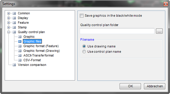
Tip: The file names of graphics are combined to include the ID for each feature. This ID can be different to the stamp text. The main part of the name is taken from that of the quality control plan or the drawing (from Version 10.9.1). Configuration is done in a settings dialogue.
The various options are combinable and included in table below:
Tip: This parameter is optional. If it is not provided, the individual features are provided with stamps (Option 0x000002) in BMP format (Option 0x000010)
| Option (HEX) | Value (Decimal) | Description | File name |
|---|---|---|---|
| 0x000001 | 1 | Issues a graphic for each feature. (without stamp) | [SOURCEFILE]-“ID”.[FORMAT] |
| 0x000002 | 2 | Issues a graphic for each feature. (with stamp) | [SOURCEFILE]-“ID”.[FORMAT] or [SOURCEFILE]-“ID”-STAMP.[FORMAT] (for graphics issue either with or without stamps) |
| 0x000004 | 4 | Issues a graphic for the complete drawing. (without stamp) | [SOURCEFILE].[FORMAT] |
| 0x000008 | 8 | Issues a graphic for the complete drawing (with stamp) | [SOURCEFILE]-STAMP.[FORMAT] |
| 0x000010 | 16 | Graphics issued in BMP format. | [FORMAT] = ”.bmp” |
| 0x000020 | 32 | Graphics issued in TIFF format. | [FORMAT] = ”.tif” |
| 0x000040 | 64 | Graphics issued in JPEG format. | [FORMAT] = ”.jpg” |
| 0x000080 | 128 | Graphics issued in PNG format. | [FORMAT] = ”.png” |
| 0x000100 | 256 | Graphics issued in EMF format. | [FORMAT] = ”.emf” |
| 0x000200 | 512 | Graphics issued in WMF format. | [FORMAT] = ”.wmf” |
| 0x001000 | 4096 | Drawing with stamps saved in DWG format. | [SOURCEFILE]-STAMP.dwg |
| 0x002000 | 8192 | Drawing with stamps saved in DXF format. | [SOURCEFILE]-STAMP.dxf |
/STPNO= (from Version 10.4)
/STPNO=10.0
Start value for stamps; this value can be overwritten in the settings in the XML file.
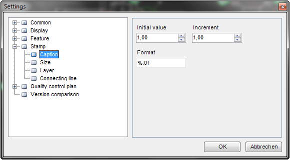
Tip: This value can be in decimal format! Use a point as decimal character!
/STPIN= (from Version 10.4)
/STPIN=0.3
Increment for stamp number; this value can be overwritten in the settings in the XML file.


/STPFMT= (from Version 10.4)
/STPFMT=”%.1f”
Format string for stamp text, this value can be overwritten in the settings in the XML file.

Tip: The format string must be bracketed in quote marks.
/SFT= (from Version 10.4)
/SFT=0
- 0 = Do not display feature table
- 1 = Display feature table
Tip: This parameter is read off only at programme start and does not change the standard setting. Users can show or hide the table at will.
/COMPARE= (from Version 10.5.2)
This parameter can provide a ICP file that already belongs to a stamped drawing. If the latest edit version of drawing is stamped, it is checked to see if the stamp already exists in the old version. If yes, the same stamp number is issued and is also write-protected.
Tip: Do not use this parameter with /OPEN! 
/UPDATE= (from Version 11.10.0)
This parameter can provide a text file that contains a list of features to delete from an existing quality control plan.
Content of the file:
DELETE-STAMP:<Stamp-No. 1>;<Stamp-No. 2>;...;<Stamp-No. X>
Optional:
DELETE-ID:<Feature-ID 1>;<Feature-ID 2>;...;<Feature-ID X>
Tip: Only use this parameter with /OPEN!
/UXML= (since version 11.11.0)
This parameter refers to a XML-configuration file, which contains the user settings for infra-CONVERT (like window positions, active filters, …
/TYPES= (since version 11.11.0)
This parameter refers to the configuration file for the feature type definitions.
Request parameters: Example
Provide a drawing (/CAD=) and the export file (/PRF=) in PRF format:
/CAD=“D:\Drawing\ELIAS GmbH\Example-1.dxf” /PRF=”%TEMP%\INFRA- CONVERT .PRF” Provision of drawing (/CAD=), export file (/PRF=) in PRF format, path for graphic (/BMP=) and language (/LANG=):
/CAD=“D:\Drawing\ELIAS GmbH\Example-1.dxf” /PRF=”%TEMP%\INFRA- CONVERT.PRF” /BMP=”%TEMP%” /LANG=DE Provision of a drawing (/CAD=), export file (/PRF=) in PRF format, path fro the graphic (/BMP=), the language (/LANG=) and a configuration file (/XML=):
/CAD=“D:\Drawing\ELIAS GmbH\Example-1.dxf” /PRF=”%TEMP%\INFRA- CONVERT.PRF” /BMP=”%TEMP%” /LANG=DE /XML=“INFRA-CONVERT.XML”
Provision of a drawing (/CAD=), the export file (/PRF=) in PRF format, path for the graphic (/BMP=) and graphic format (/GRAPHICEXPORT), here TIFF (32) + complete drawing +stamps (8) + graphic per feature with stamp (2):
/CAD=“D:\Drawing\ELIAS GmbH\Example-1.dxf” /PRF=”%TEMP%\INFRA- CONVERT.PRF” /BMP=”%TEMP%” /GRAPHICEXPORT=42
PRF format
Construction of feature row in PRF format
The feature row consists of the following:
ID<Separator>Feature type<Separator>Class<Separator>Description<Separator>Text<Separator>Nominal value<Separator>
Upper tolerance<Separator>Lower tolerance<Separator>Fit<Separator>Stamp<Separator>Graphic file name<Separator>
Comment<Separator>Table<Separator>Column<Separator>Drawing quadrant<Separator>Position X<Separator>Position Y<Separator>
Target point X<Separator>Target point Y<Separator>Radius<Row change>
TAB is used <Separator>.
Tip: Drawing quadrant values were added in Version 10.8.11.
Tip: Values for Position X to Target point Y were added in Version 10.9.1.
Description of individual elements:
ID (1. Value)
- Whole number without prefix (Type: unsigned int)
Feature type (2. Value)
- Whole number value (Type: int)
- Meaning:
- -1 (undefined)
- 0 (attributive)
- 1 (quantitative)
- … (further additions possible)
Class 3 (3. Value)
- Whole number value (Type: int)
- Meaning:
- -1 (undefined)
- 0 = Linear
- 1 = Radius
- 2 = Diameter
- 3 = Angle
- 4 = Minor axis ellipse
- 5 = Major axis ellipse
- 6 = Taper angle
- 7 = Straightness
- 8 = Flatness
- 9 = Circularity
- 10 = Cylindricity
- 11 = Profile of line
- 12 = Profile of surface
- 13 = Parallelism
- 14 = Perpendicularity
- 15 = Angularity
- 16 = Circular runout
- 17 = Axial runout
- 18 = Total circular runout
- 19 = Total axial runout
- 20 = Symmetry
- 21 = Concentricity
- 22 = Position
- 23 = Measured mean roughness Rz
- 24 = Profile height Rt=Pt
- 25 = Arith. mean roughness Ra
- 26 = Profile height Pt
- 27 = Core roughness Rk
- 28 = Red. peak height
- 29 = Red. valley depth
- 30 = Waviness depth Wt
- 31 = Max. roughness Rmax
- 32 = Basic roughness R3z (from Version10.6.2)
- 33 = Chamfer (from Version 10.7.1)
- 34 = Chamfer edges (from Version 10.7.2)
- 35 = Curve (from Version 10.8.2)
- 36 = Edge (from Version 10.8.4)
- 37 = Torque (from Version 10.8.5)
- 38 = Thread (from Version 10.8.5)
- 39 = Hardness, Brinell (from Version 10.8.5)
- 40 = Hardness, Rockwell (HRA) (from Version 10.8.5)
- 41 = Hardness, Rockwell (HRB) (from Version 10.8.5)
- 42 = Hardness, Rockwell (HRC) (from Version 10.8.5)
- 43 = Hardness, Rockwell (HRF) (from Version 10.8.5)
- 44 = Hardness, Vickers (HV) (from Version 10.8.5)
- 45 = Hardness, Martens (HM) (from Version 10.8.5)
- 46 = Ball indentation hardness (H) (from Version 10.8.5)
- 47 = Hardness Shore (Shore A) (from Version 10.8.5)
- 48 = Hardness Shore (Shore D) (from Version 10.8.5)
- 49 = Proof stress Rp0.1 (from Version 10.8.11)
- 50 = Proof stress Rp0.2 (from Version 10.8.11)
- 51 = Proof stress Rp1.0 (from Version 10.8.11)
- 52 = Upper yield strength (from Version 10.8.11)
- 53 = Lower yield strength ReL (from Version 10.8.11)
- 54 = Tensile strength Rm (from Version 10.8.11)
- 55 = Deformation A (from Version 10.8.11)
- 56 = Coordinates (from Version 10.8.11)
- 57 = X-coordinate (from Version 10.8.11)
- 58 = Y-coordinate (from Version 10.8.11)
- 59 = Z-coordinate (from Version 10.8.11)
- 60 = Spring rate (from Version 10.8.11)
- 61 = Temperature [°C] (fromVersion10.8.11)
- 62 = Temperature [F] (from Version 10.8.11)
- 63 = Pressure (from Version 10.8.11)
- 64 = Layer thickness (from Version 10.8.11)
- 65 = Volume (from Version 10.8.11)
- 66 = Mass (from Version 10.8.11)
- 67 = Force (from Version 10.8.11)
- 68 = Viscosity (from Version 10.8.11)
- 69 = Balance (from Version 10.8.11)
- 70 = Material fraction Pmr (from Version 11.3.2)
- 71 = Material fraction Mr1 (from Version 11.3.2)
- 72 = Material fraction Mr2 (from Version 11.3.2)
- 73 = Theoretical dimension (from Version 11.5.0)
- 74 = Material (from Version 11.5.0)
- 75 = Information (from Version 11.10.0)
- … (Additions planned)
Description (4. Value)
- Text (Type: Text, dynamic length)
- Text length for the Description can be defined by the used.
- This parameter is optional.
Text (5. Value)
- Text (Type: Text, dynamic length)
- Text, derived from the drawing. This text can also be freely defined by the user.
- For attributive features only the text should be evaluated.
Nominal value (6. Wert)
- Number value (Type: double)
- Decimal, the decimal separator is a ‘point’ (.).
- This parameter is optional for attributive features.
Upper tolerance (7. Value)
- Number value (Type: double)
- Decimal, the decimal separator is a ‘point’ (.).
- This parameter is optional.
Lower tolerance (8. Value)
- Number value (Type: double)
- Decimal, the decimal separator is a ‘point’ (.).
- This parameter is optional.
Fit (e.g. B. H7) (9. Value)
- Text (Type: Text, dynamic length)
- This parameter is optional.
- If the engineering fit is known, then fields 7 and 8 contain the corresponding tolerances.
Stamp text (10. Value)
- Text (Type: Text, dynamic length)
- This parameter is optional.
Graphic file name (11. Value)
- File name (Type: Text, dynamic length)
- The site where the file is saved can be given when the programme starts.
- The name combines the name of the drawing and the ID.
Comments (12. Value)
- Text (Type: Text, dynamic length)
- This parameter is optional.
Table (Source for tolerances) (13. Value)
- Text (Type: Text, dynamic length)
- This is the source for tolerances issued. Either engineering fit accord. DIN IS0 286, or tolerances selected from the features dialogue (first Combo-Box (Table)).
- If tolerances are read from the dimensions, this parameter remains empty.
Column (Tolerance class) (14. Value)
- Text (Type: Text, dynamic length)
- If the tolerances are read from a table, this is where tolerance class is given: Mean, … . Value from second Combo-Box (Column).
- In case of Fit, H7 is given, for example.
Drawing quadrant (15. Value) (from Version 10.8.11)
- Text (Type: Text, dynamic length)
Position X/Position Y (16./17. Value) (from Version 10.9.1)
- Number value (Type: double)
- Stamp mid-point
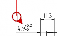
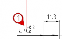
- The mid-point of a stamp is given relative to the image of the complete drawing. The coordinates are related to the top left corner of the picture.
Target point X/target point Y (18./19. Value) (from Version 10.9.1)
- Number value (Type: double)
- Stamp target point
- The target point of a stamp is related to the image of the complete drawing. The coordinates are related to the top left corner of the picture.
Radius (20. Value) (from Version 11.5.0)
- Number value (Type: double)
- Radius of the stamp circle in pixels
CSV-Format (from Version 10.5)
Headers in CSV format (from Version 10.9)
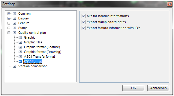
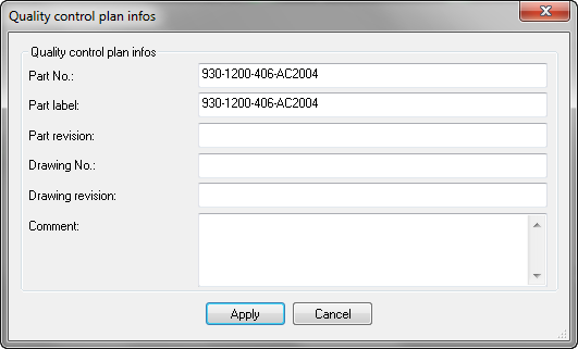
An optional header is available in CVS. The settings can be found in the “Extras” menu, under /Settings/Quality control plan/CSV format”.
The header is constructed as follows:
Part number<Separator>Part label<Separator>Part revision<Separator>
Drawing number<Separator>Drawing revision<Separator>Comment<Separator>
Tip: CSV format is language-dependent. One row contains the titles. The feature graphic is only produced if the graphic is created. For integration in other software packages we recommend PRF format.
Construction of a feature row in CSV format
The feature row has the following components:
Stamp text<Separator>Description<Separator>Text<Separator>Nominal value<Separator>
Upper tolerance<Separator>Lower tolerance <Separator>Upper limit value<Separator>Lower limit value <Separator>
Feature type<Separator>Class<Separator>Fit<Separator>Description<Separator>Table<Separator>Column<Separator>
Drawing quadrant<Separator>Feature graphic<Separator>Position X<Separator>Position Y<Separator>Target point X<Separator>Target point Y<Separator>Radius
Tip: The Drawing quadrant value was introduced in Version 10.8.11.
Tip: Position X to target point Y were introduced in Version 10.9.1 and can be activated via the “Extras” menu under /Settings / Quality control plan/CSV format.
A semi-colon is used as <Separator>.
Tip: One row contains the titles. The feature graphic is only produced if the graphic is created. For integration in other software packages we recommend PRF format.
Description of individual elements in the features row:
Stamp text (Column A)
- Text
- This parameter is optional.
Description (column B)
- Text (The user is free to choose the text for Description.)
- This parameter is optional.
Text (Column C)
- Text (Text derived from the drawing. The user is also free to choose the text.)
- For attributive features only the text should be evaluated.
Nominal value (Column D)
- Number value (Decimal, the decimal separator is a comma (,).)
- This parameter is optional for attributive features.
Upper tolerance (Column E)
- Number value (Decimal numbers, a comma (,) is used as decimal separator.)
- This parameter is optional.
Lower tolerance (Column F)
- Number value (Decimal numbers, a comma (,) is used as decimal separator.)
- This parameter is optional.
Upper limit (Column G)
- This value is calculated (Nominal value + upper tolerance).
Lower limit (Column H)
- This value is calculated (Nominal value - lower tolerance).
Feature type (Column I)
- Text
- Value:
- Variable
- Attributive
Class (Column J)
- Text
- Value:
- Linear
- Radius
- Diameter
- Angle
- Minor diameter ellipse
- Major diameter ellipse
- Taper angle
- Straightness
- Flatness
- Circularity
- Cylindricity
- Profile of line
- Profile of surface
- Parallelism
- Perpendicularity
- Angularity
- Circular runout
- Axial runout
- Total circular runout
- Total axial runout
- Symmetry
- Concentricity
- Position
- Measured mean roughness Rz
- Profile height Rt=Pt
- Arith. mean roughness Ra
- Profile depth Pt
- Core roughness Rk
- Red. peak height
- Red. valley depth
- Wave depth Wt
- Maximum roughness Rmax
- Basic roughness R3z (from Version 10.6.2)
- Chamfer (from Version 10.7.1)
- Chamfer edges (from Version 10.7.2)
- Curve (from Version 10.8.2)
- Edge (from Version 10.8.4)
- Torque (from Version 10.8.5)
- Thread (from Version 10.8.5)
- Hardness, Brinell (from Version 10.8.5)
- Hardness, Rockwell (HRA) (from Version 10.8.5)
- Hardness, Rockwell (HRB) (from Version 10.8.5)
- Hardness, Rockwell (HRC) (from Version 10.8.5)
- Hardness, Rockwell (HRF) (from Version 10.8.5)
- Hardness, Vickers (HV) (from Version 10.8.5)
- Hardness, Martens (HM) (from Version 10.8.5)
- Ball indentation hardness (H) (from Version 10.8.5)
- Hardness, Shore (Shore A) (from Version 10.8.5)
- Hardness, Shore (Shore D) (from Version 10.8.5)
- Proof stress Rp0.1 (from Version 10.8.11)
- Proof stress Rp0.2 (from Version 10.8.11)
- Proof stress Rp1.0 (from Version 10.8.11)
- Upper yield stress ReH (from Version 10.8.11)
- Upper yield stress ReL (from Version 10.8.11)
- Tensile strength Rm (from Version 10.8.11)
- Deformation A (from Version 10.8.11)
- Coordinates (from Version 10.8.11)
- X-Coordinate (from Version 10.8.11)
- Y-Coordinate (from Version 10.8.11)
- Z-Coordinate (from Version 10.8.11)
- Spring rate (from Version 10.8.11)
- Temperature [°C] (from Version 10.8.11)
- Temperature [F] (from Version 10.8.11)
- Pressure (from Version 10.8.11)
- Layer thickness (from Version 10.8.11)
- Volume (from Version 10.8.11)
- Mass (from Version 10.8.11)
- Force (from Version 10.8.11)
- Viscosity (from Version 10.8.11)
- Balance (from Version 10.8.11)
- Material fraction Pmr (from Version 11.3.2)
- Material fraction Mr1 (from Version 11.3.2)
- Material fraction Mr2 (from Version 11.3.2)
- Theoretical dimension (from Version 11.5.0)
- Material (from Version 11.5.0)
- Information (from Version 11.10.0)
- … (Additions planned)
Fit (e.g. H7) (Column K)
- Text
- This parameter is optional.
- If engineering fit is known then fields 7 and 8 contain the corresponding tolerances for this fit.
Description (Column L)
- Text
- This parameter is optional.
Table (Source for tolerances) (Column M)
- Text
- This the given source for the determined tolerances. Either fit accord. to DIN IS0 286, or the tolerance table selected from the features catalogue (First Combo-Box (Table ).
- If the tolerances are read off the dimensions, this parameter remains empty.
Column (Tolerance class) (Column N)
- Text
- If tolerances are read from a tolerance table, the tolerance class is given here: Middle, … . Value from second Combo-Box (Column)
- In the case of Fit H7 is given, for example.
Drawing quadrant (Column O) (from Version 10.8.11)
- Text
- If no coordinate system is defined then this value is left empty.
Feature graphic (Column P)
- File name
- The site where the file is saved can be given when the programme starts.
- The name combines the name of the drawing and the ID.
- This value is only given when feature graphics are also created.
Position X/Position Y (from Version 10.9.2)
- Stamp mid-point
- The mid-point of a stamp is given relative to the image of the complete drawing. The coordinates are related to the top left corner of the picture.
Target point X/Target point Y (from Version 10.9.2)
- Stamp target point
- The target point of a stamp is related to the image of the complete graphic. The coordinates are related to the top left corner of the picture.
Radius (from Version 11.5.0)
- Radius of the stamp circle in pixels.
DFD format
File header:
| K0100 | Total no. features in the file | [5] | I |
| K1001 | Part number | [30] | A |
| K1002 | Part description | [80] | A |
| K1004 | Changes status d. Part | [20] | A |
| K1041 | Drawing number | [30] | A |
| K1042 | Drawing changes | [20] | A |
| K1900 | Comments | [255] | A |
Feature:
| K2001 | Feature number | [20] | A | ⇒ Stamp text |
| K2002 | Feature description | [80] | A | ⇒ Description |
| K2003 | Feature description | [20] | A | ⇒ Text |
| K2004 | Feature type | [1] | I | ⇒ Feature type |
| K2009 | Feature size | [3] | I | ⇒ Class |
| K2091 | Feature index | [20] | A | ⇒ internal ID (definitive) |
| K2101 | Value | [22] | F | ⇒ Nominal value |
| K2110 | Lower specification limit | [22] | F | ⇒ Nominal value + upper tolerance |
| K2111 | Upper specification limit | [22] | F | ⇒ Nominal value – lower tolerance |
| K2112 | Lower dimension | [22] | F | ⇒ lower tolerance |
| K2113 | Upper dimension | [22] | F | ⇒ upper tolerance |
| K2120 | Type of limit, lower | [1] | I | |
| K2121 | Type of limit, upper | [1] | I | |
| K2243 | Drawing file name | [80] | A | |
| K2810 | User field description 2 | [50] | A | |
| K2811 | User field type 2 | [1] | A | |
| K2812 | User field content 2 | [255] | A | |
| K2900 | Comments | [255] | A | ⇒ Comment |
Codes:
I: (Integer, with [5] to max. 32767),
W: (Word, to max. 65634),
F: (Floating point number, Value range approx. 1.7 * 10±308),
D: (Date/time format) and
A (Alphanumeric) give the type of field, in other words, numbers entered in this field must be in the designated format.
K2009
| ID | Class | K2009 |
|---|---|---|
| -1 | (not defined) | 0 |
| 0 | Linear (Length ) | 200 |
| 1 | Radius | 201 |
| 2 | Diameter | 202 |
| 3 | Angle | 203 |
| 4 | Minor diameter ellipse | 204 |
| 5 | Major diameter ellipse | 205 |
| 6 | Taper angle | 206 |
| 7 | Straightness | 100 |
| 8 | Flatness | 101 |
| 9 | Circularity | 102 |
| 10 | Cylindricity (cylindrical form) | 103 |
| 11 | Profile of line (line form) | 104 |
| 12 | Profile of surface (surface) | 105 |
| 13 | Parallelism | 108 |
| 14 | Perpendicularity | 107 |
| 15 | Angularity | 106 |
| 16 | Circular runout | 112 |
| 17 | Axial runout | 118 |
| 18 | Total circular runout (total runout) | 113 |
| 19 | Total axial runout (total runout) | 113 |
| 20 | Symmetry | 111 |
| 21 | Concentricity | 110 |
| 22 | Position (Position (entry)) | 109 |
| 23 | Measured mean roughness Rz (roughness Rz) | 150 |
| 24 | Profile height Rt=Pt | 151 |
| 25 | Arith. mean roughness Ra (a. mean profile ordinate Ra) | 152 |
| 26 | Profile depth Pt | 153 |
| 27 | Core roughness Rk | 154 |
| 28 | Red. peak height | 155 |
| 29 | Red. valley depth | 156 |
| 30 | Waviness Wt (roughness Wt) | 157 |
| 31 | Maximum roughness Rmax | 158 |
| 32 | Basic roughness R3z (from Version 10.6.2) | 159 |
| 33 | Chamfer (from Version 10.7.1) | 0 |
| 34 | Chamfer edges (from Version 10.7.2) | 0 |
| 35 | Curve (from Version 10.8.2) (Radius) | 201 |
| 36 | Edge (from Version 10.8.4) | 0 |
| 37 | Torque (from Version 10.8.5) | 301 |
| 38 | Thread (from Version 10.8.5) | 0 |
| 39 | Hardness, Brinell (from Version 10.8.5) (Hardness) | 285 |
| 40 | Hardness, Rockwell (HRA) (from Version 10.8.5) (Hardness) | 285 |
| 41 | Hardness, Rockwell (HRB) (from Version 10.8.5) (Hardness) | 285 |
| 42 | Hardness, Rockwell (HRC) (from Version 10.8.5) (Hardness) | 285 |
| 43 | Hardness, Rockwell (HRF) (from Version 10.8.5) (Hardness) | 285 |
| 44 | Hardness, Vickers (HV) (from Version 10.8.5) (Hardness) | 285 |
| 45 | Hardness, Martens (HM) (from Version 10.8.5) (Hardness) | 285 |
| 46 | Ball indentation hardness (H) (from Version 10.8.5) (Hardness) | 285 |
| 47 | Hardness, Shore (Shore A) (from Version 10.8.5) (Hardness) | 285 |
| 48 | Hardness, Shore (Shore D) (from Version 10.8.5) (Hardness) | 285 |
| 49 | Proof stress Rp0.1 (from Version 10.8.11) | 282 |
| 50 | Proof stress Rp0.2 (from Version 10.8.11) | 282 |
| 51 | Proof stress Rp1.0 (from Version 10.8.11) | 282 |
| 52 | Upper yield strength ReH (from Version 10.8.11) | 282 |
| 53 | Lower yield strength ReL (from Version 10.8.11) | 282 |
| 54 | Tensile strength Rm (from Version 10.8.11) | 282 |
| 55 | Deformation A (from Version 10.8.11) | 0 |
| 56 | Coordinates (from Version 10.8.11) | 117 |
| 57 | X-Coordinate (from Version 10.8.11) | 120 |
| 58 | Y-Coordinate (from Version 10.8.11) | 121 |
| 59 | Z-Coordinate (from Version 10.8.11) | 122 |
| 60 | Spring rate (from Version 10.8.11) | 220 |
| 61 | Temperature [°C] (from Version 10.8.11) | 250 |
| 62 | Temperature [F] (from Version 10.8.11) | 251 |
| 63 | Pressure (from Version 10.8.11) | 255 |
| 64 | Layer thickness (from Version 10.8.11) | 260 |
| 65 | Volume (from Version 10.8.11) | 270 |
| 66 | Mass (from Version 10.8.11) | 280 |
| 67 | Force (from Version 10.8.11) | 282 |
| 68 | Viscosity (from Version 10.8.11) | 290 |
| 69 | Balance (from Version 10.8.11) | 300 |
| 70 | Material fraction Pmr | 160 |
| 71 | Material fraction Mr1 | 161 |
| 72 | Material fraction Mr2 | 162 |
